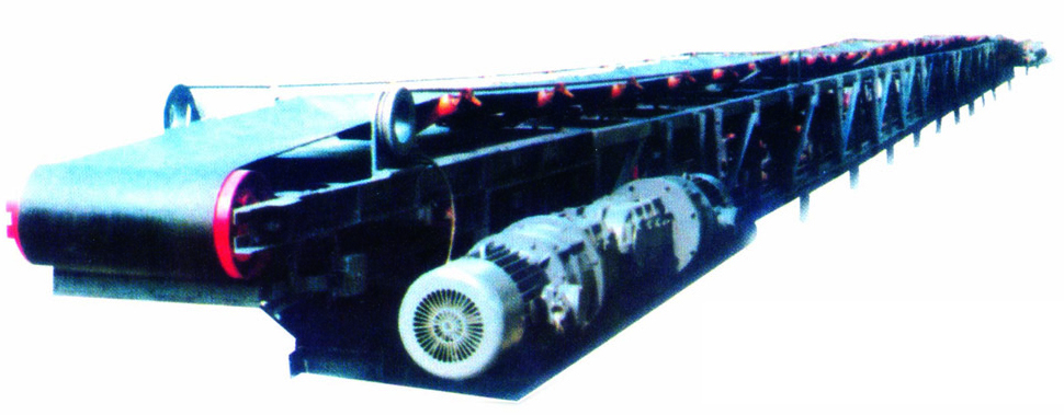
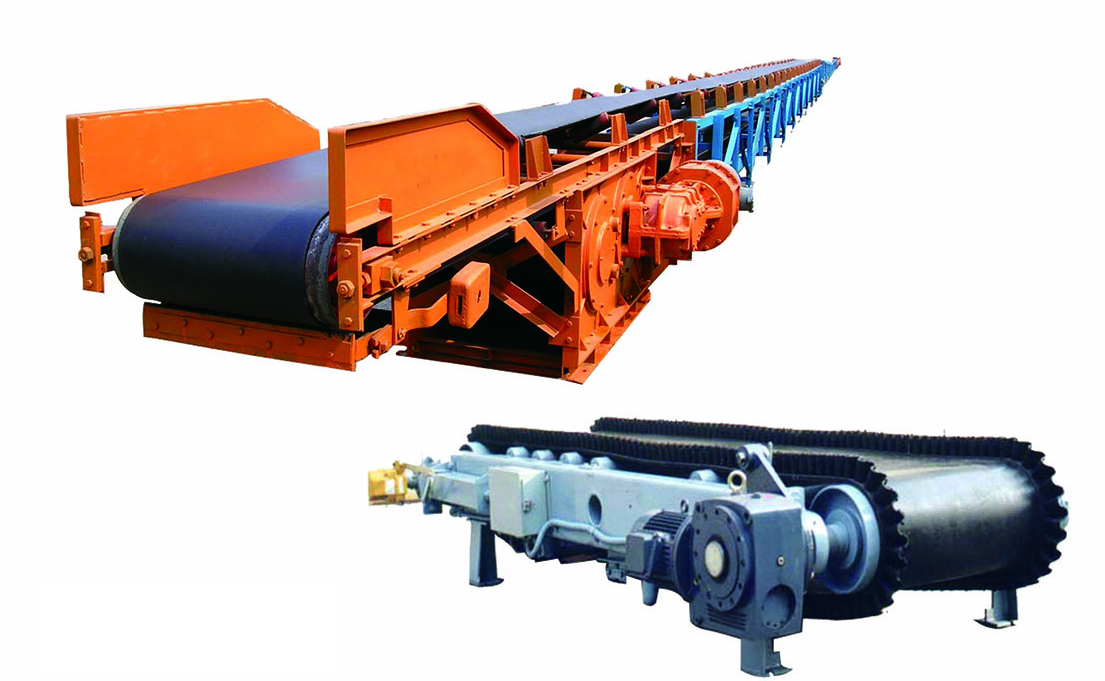
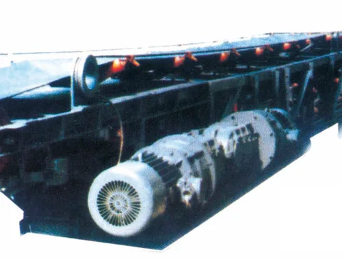
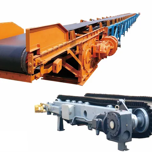
• Mining Belt Conveyor
  • Mining Belt Conveyor
  • Mining Belt Conveyor
  • Mining Belt Conveyor

Mining Belt Conveyor

A belt conveyor is a friction-driven machine that transports materials continuously. It mainly consists of frame, conveyor belt, idlers, pulleys, tensioning device, transmission device and other components.

It can form a complete material conveying route along a fixed conveying line from the initial feeding point to the final discharging point. It is suitable for conveying both bulk loose materials and unit goods.

Apart from simple material transportation, it can also coordinate with the technological procedures of various industrial production lines to form rhythmic assembly conveying lines.
$1.00
Shandong Luyi Machinery Co., Ltd.

Shandong Luyi Machinery Co., Ltd.

View Supplier
Year Established Established in 2006
Employees 101-500 People
Factory Area 10,000-50,000 m²
Annual Revenue US$10 Million - US$50 Million
Main Markets Southeast Asia / Africa
Details
Trade Information

1. Head Drive Unit

The head drive unit is made up of drive drum, reducer, fluid coupling, frame and head cleaner. It serves as the driving part of the conveyor. The motor of the drive unit drives the drive drum via the fluid coupling and reducer.
The fluid coupling is a safety-type coupling, and all couplings equipped on this equipment hold certified safety marking certificates for mining products.
Warning: The fluid coupling housing is fitted with an oil filling port and fusible alloy safety plug. The melting temperature of the fusible alloy is 115℃±5℃.
The reducer adopts three-stage gear transmission: the first stage is spiral bevel gear, the second and third stages are helical cylindrical gear and spur cylindrical gear respectively.
The drive drum is of welded construction with a vulcanized rubber lining on its surface. It increases friction between the belt and drum to prevent slipping and reduce initial tension.
The frame is a welded assembly of side plates and base frame. The drive assembly consisting of motor, reducer and fluid coupling can be mounted on either the left or right side plate of the frame according to site requirements.
The discharge end comprises an extended discharge frame at the foremost part of the head and discharge (deflection) drums mounted on the frame. The axial position of the discharge drum can be adjusted forward and backward to correct belt deviation.
Two types of head cleaners are available: weight hammer cleaners and plow cleaners, which remove coal adhered to both sides of the belt. All deflection drums at the head are equipped with coal scrapers to avoid coal buildup.

2. Belt Storage Unit

The belt storage unit includes storage deflection frame, storage bin frame, support trolley and tension trolley.
The storage deflection frame and storage bin frame are mainly welded structures connected by bolts. Deflection drums are installed separately on the storage deflection frame and tension trolley to jointly guide the reciprocating movement of the belt. Trough idlers and flat idlers are fitted on the upper part of the deflection frame to support the belt. Rails are arranged inside the storage bin frame for the travel of support trolleys and tension trolleys.
Each support trolley consists of two lower idlers, trolley frame and rollers. It supports the stored belt to avoid excessive sagging. Support trolleys shall be distributed at roughly equal intervals between the tension trolley and storage deflection frame; manual repositioning of trolleys is required after the tension trolley moves.
The tension trolley is composed of frame, wheels, pulley block and deflection drum. A tension winch pulls the tension trolley along the rails through a steel wire rope pulley block to store or release the belt and maintain proper belt tension. The pulley block is assembled with a pulley bracket and four pulleys, hinged to the trolley frame via a pin shaft. This combines uneven traction forces acting on the four pulleys into a resultant force applied at the trolley center through the pin shaft, effectively preventing belt deviation on the deflection drum. Four anti-climb hooks are installed on the tension trolley to prevent derailment.
The axial mounting position of each deflection drum is adjustable for belt deviation correction, and all drums are fitted with coal scrapers against coal adhesion. In addition, the idler seats for lower idlers on support trolleys are equipped with cotter pins.
Notice: Ensure cotter pins are fully inserted before startup to prevent lower idlers from being knocked off the supports by belt vibration during conveyor start-up or shutdown.

3. Tensioning Unit

The tensioning unit is composed of frame, pulley block and tension winch. The tension winch is a low-speed winch with worm-and-worm gear drive plus open gear drive. The worm-and-worm gear structure features self-locking in reverse rotation. A friction damping device is fitted at one end of the worm shaft; its friction torque can be adjusted via adjusting screws on the gland to stop the winch from reverse rotation after shutdown and maintain stable wire rope tension.
A clutch device is mounted on one side of the tension drum. The clutch must be disengaged during belt take-up to separate the drum from its shaft. Three brake bands are fitted on the same side to stop free rotation and wire rope tangling, providing semi-braking effect during rope payout.
Notice: Belt tension shall be adjusted moderately according to actual working conditions; avoid excessively tight or loose manual adjustment.

4. Belt Take-up & Release Unit

The belt take-up and release unit is installed behind the tension winch (not equipped on some conveyor models). It consists of frame, self-aligning idler set, belt reel, reducer, motor and screw rods, used to remove or install belt sections on the conveyor. One screw rod is fitted at each end of the frame to clamp the main belt during belt replacement. The self-aligning idler set guides the belt during reel winding and unwinding.
During operation, push the reel into the frame; jack up one end with a tail bracket and support the other end against the tip of the dial shaft. Start the motor, which drives the reel to wind the belt through the reducer and a pair of open reduction gears, and finally the dial on the dial shaft.
For belt payout, the motor remains off and the reel is driven to reverse by external force. The pin on the dial must be removed to disconnect the reel from the dial. Movable rails are hung on the main frame via hanging brackets when idle to reduce overall machine width. Lifting devices shall be installed above the movable rails to suspend the reel. The roadway width can be widened appropriately to facilitate belt take-up and release operations.

5. Intermediate Body

As the quick-disassembling movable section of the conveyor, the intermediate body is assembled with steel pipes, H-type supports, lower idlers and hook-type trough idlers. Detachable steel pipe sections are seated in pipe holders on H-type supports via elastic pins fixed on the pipes. Proper pin positioning allows convenient insertion and removal of steel pipes by rotation.
The hinged trough idlers have a trough angle of 30°, hung on steel pipes via hooks for easy mounting and dismounting, enabling rapid assembly and disassembly. Trough idlers can also slide forward and backward to adjust positions and rectify belt deviation.

6. Tail Assembly

The tail assembly includes base supports, guide rails, drum seats, buffer idlers and cleaners. Multiple types of guide rails are rigidly connected with base supports and drum seats to form a five-section tail framework, hinged together via round shoulder pins into an integrated structure for the scraper loader to travel on. Pipe holders are welded on the foremost frame, connected to the steel pipe body via pins for easy assembly and disassembly.
The tail (deflection) drum is mounted on the drum seat with adjustable axial position and a matching coal scraper. Pulleys for tail movement can be fitted at either front or rear end of the tail frame: rear mounting for forward conveying extension, front mounting for backward retraction. The tail can be pulled and moved by a prop-drawing winch or hydraulic cylinders.
MOQ
1 Sets
Max Order Quantity
999 Sets
  • Mining Belt Conveyor
  • Mining Belt Conveyor

Description

1. Head Drive Unit

The head drive unit is made up of drive drum, reducer, fluid coupling, frame and head cleaner. It serves as the driving part of the conveyor. The motor of the drive unit drives the drive drum via the fluid coupling and reducer.
The fluid coupling is a safety-type coupling, and all couplings equipped on this equipment hold certified safety marking certificates for mining products.
Warning: The fluid coupling housing is fitted with an oil filling port and fusible alloy safety plug. The melting temperature of the fusible alloy is 115℃±5℃.
The reducer adopts three-stage gear transmission: the first stage is spiral bevel gear, the second and third stages are helical cylindrical gear and spur cylindrical gear respectively.
The drive drum is of welded construction with a vulcanized rubber lining on its surface. It increases friction between the belt and drum to prevent slipping and reduce initial tension.
The frame is a welded assembly of side plates and base frame. The drive assembly consisting of motor, reducer and fluid coupling can be mounted on either the left or right side plate of the frame according to site requirements.
The discharge end comprises an extended discharge frame at the foremost part of the head and discharge (deflection) drums mounted on the frame. The axial position of the discharge drum can be adjusted forward and backward to correct belt deviation.
Two types of head cleaners are available: weight hammer cleaners and plow cleaners, which remove coal adhered to both sides of the belt. All deflection drums at the head are equipped with coal scrapers to avoid coal buildup.

2. Belt Storage Unit

The belt storage unit includes storage deflection frame, storage bin frame, support trolley and tension trolley.
The storage deflection frame and storage bin frame are mainly welded structures connected by bolts. Deflection drums are installed separately on the storage deflection frame and tension trolley to jointly guide the reciprocating movement of the belt. Trough idlers and flat idlers are fitted on the upper part of the deflection frame to support the belt. Rails are arranged inside the storage bin frame for the travel of support trolleys and tension trolleys.
Each support trolley consists of two lower idlers, trolley frame and rollers. It supports the stored belt to avoid excessive sagging. Support trolleys shall be distributed at roughly equal intervals between the tension trolley and storage deflection frame; manual repositioning of trolleys is required after the tension trolley moves.
The tension trolley is composed of frame, wheels, pulley block and deflection drum. A tension winch pulls the tension trolley along the rails through a steel wire rope pulley block to store or release the belt and maintain proper belt tension. The pulley block is assembled with a pulley bracket and four pulleys, hinged to the trolley frame via a pin shaft. This combines uneven traction forces acting on the four pulleys into a resultant force applied at the trolley center through the pin shaft, effectively preventing belt deviation on the deflection drum. Four anti-climb hooks are installed on the tension trolley to prevent derailment.
The axial mounting position of each deflection drum is adjustable for belt deviation correction, and all drums are fitted with coal scrapers against coal adhesion. In addition, the idler seats for lower idlers on support trolleys are equipped with cotter pins.
Notice: Ensure cotter pins are fully inserted before startup to prevent lower idlers from being knocked off the supports by belt vibration during conveyor start-up or shutdown.

3. Tensioning Unit

The tensioning unit is composed of frame, pulley block and tension winch. The tension winch is a low-speed winch with worm-and-worm gear drive plus open gear drive. The worm-and-worm gear structure features self-locking in reverse rotation. A friction damping device is fitted at one end of the worm shaft; its friction torque can be adjusted via adjusting screws on the gland to stop the winch from reverse rotation after shutdown and maintain stable wire rope tension.
A clutch device is mounted on one side of the tension drum. The clutch must be disengaged during belt take-up to separate the drum from its shaft. Three brake bands are fitted on the same side to stop free rotation and wire rope tangling, providing semi-braking effect during rope payout.
Notice: Belt tension shall be adjusted moderately according to actual working conditions; avoid excessively tight or loose manual adjustment.

4. Belt Take-up & Release Unit

The belt take-up and release unit is installed behind the tension winch (not equipped on some conveyor models). It consists of frame, self-aligning idler set, belt reel, reducer, motor and screw rods, used to remove or install belt sections on the conveyor. One screw rod is fitted at each end of the frame to clamp the main belt during belt replacement. The self-aligning idler set guides the belt during reel winding and unwinding.
During operation, push the reel into the frame; jack up one end with a tail bracket and support the other end against the tip of the dial shaft. Start the motor, which drives the reel to wind the belt through the reducer and a pair of open reduction gears, and finally the dial on the dial shaft.
For belt payout, the motor remains off and the reel is driven to reverse by external force. The pin on the dial must be removed to disconnect the reel from the dial. Movable rails are hung on the main frame via hanging brackets when idle to reduce overall machine width. Lifting devices shall be installed above the movable rails to suspend the reel. The roadway width can be widened appropriately to facilitate belt take-up and release operations.

5. Intermediate Body

As the quick-disassembling movable section of the conveyor, the intermediate body is assembled with steel pipes, H-type supports, lower idlers and hook-type trough idlers. Detachable steel pipe sections are seated in pipe holders on H-type supports via elastic pins fixed on the pipes. Proper pin positioning allows convenient insertion and removal of steel pipes by rotation.
The hinged trough idlers have a trough angle of 30°, hung on steel pipes via hooks for easy mounting and dismounting, enabling rapid assembly and disassembly. Trough idlers can also slide forward and backward to adjust positions and rectify belt deviation.

6. Tail Assembly

The tail assembly includes base supports, guide rails, drum seats, buffer idlers and cleaners. Multiple types of guide rails are rigidly connected with base supports and drum seats to form a five-section tail framework, hinged together via round shoulder pins into an integrated structure for the scraper loader to travel on. Pipe holders are welded on the foremost frame, connected to the steel pipe body via pins for easy assembly and disassembly.
The tail (deflection) drum is mounted on the drum seat with adjustable axial position and a matching coal scraper. Pulleys for tail movement can be fitted at either front or rear end of the tail frame: rear mounting for forward conveying extension, front mounting for backward retraction. The tail can be pulled and moved by a prop-drawing winch or hydraulic cylinders.
RFQ